
LNG tank design is a multidisciplinary engineering process that combines cryogenic materials, containment, thermal insulation, structural analysis, pressure control, boil-off gas (BOG) management, foundation engineering, instrumentation and safety systems.
Liquefied natural gas (LNG) is normally stored at cryogenic temperatures, around -162°C at atmospheric pressure. The large temperature difference between LNG and ambient conditions creates specific requirements for material toughness, thermal contraction, insulation and structural design.
The appropriate design depends on LNG capacity, operating pressure, storage duration, filling and withdrawal rates, site conditions, containment philosophy and the standards applicable to the project.
What Is LNG Tank Design?
LNG tank design determines how a storage tank will contain LNG safely while maintaining the required temperature and operating pressure throughout its service life.
A complete design normally addresses:
- Process conditions: LNG temperature, composition, pressure, capacity and transfer rates.
- Tank configuration: geometry, containment arrangement and installation.
- Materials: cryogenic steel, stainless steel, concrete and insulation materials.
- Thermal design: insulation, heat ingress, cooldown and thermal contraction.
- Pressure and BOG: vapor generation, pressure control and boil-off gas handling.
- Structural design: hydrostatic, seismic, wind, thermal and other applicable loads.
- Foundation: soil conditions, settlement and thermal effects.
- Instrumentation: level, pressure, temperature and safety monitoring.
- Codes and standards: requirements governing design, construction, inspection and operation.
For this reason, an LNG tank should be treated as an engineered storage system rather than simply as a large vessel.
LNG Tank Design Basis
The design begins by establishing the project design basis. These parameters determine the tank configuration and the engineering calculations required.
| Design Parameter | Design Consideration |
|---|---|
| Storage Capacity | Determines tank dimensions, liquid load, insulation area, and structural requirements. |
| LNG Temperature | Controls material selection, thermal contraction, and insulation requirements. |
| Operating Pressure | Affects vapor-space design, pressure control, and relief protection. |
| Filling and Withdrawal Rate | Influences flashing, vapor generation, liquid movement, and process connections. |
| Storage Duration | Influences insulation performance and BOG management requirements. |
| Site Conditions | Includes soil, groundwater, seismic, wind, and ambient conditions. |
| Applicable Regulations | Defines design, construction, inspection, and operational requirements. |
These parameters should be established before finalizing the tank dimensions, materials and containment configuration.
LNG Tank Configuration and Containment
LNG tank configuration involves several different design dimensions. Tank orientation, insulation method and containment type should not be treated as interchangeable classifications.
For example, a tank may be vertical + above ground + double containment, while another may be vertical + above ground + full containment. Smaller cryogenic tanks may additionally use vacuum insulation.
Single-Containment Design
A single-containment tank uses a primary tank to contain the LNG, together with an engineered insulation and protection system. Its suitability depends on the project design basis, site conditions and applicable regulations.
Double-Containment Design
A double-containment system combines a primary LNG tank with a secondary containment structure designed to provide additional protection in the event of leakage from the primary tank.
Full-Containment Design
A full-containment tank incorporates a primary liquid-containment system and a secondary structure designed to contain LNG and vapor under specified conditions.
Large LNG storage projects commonly use a cryogenic steel inner tank together with a reinforced concrete outer structure. Project documentation for large U.S. LNG facilities, for example, describes 9% nickel steel inner tanks, reinforced concrete outer structures, insulation, submerged pumps and pressure/vacuum protection.
The selected containment system should be determined from the applicable standards, project risk assessment, site requirements and operating philosophy.
Materials for LNG Tank Design
Material selection is one of the most important aspects of LNG tank engineering because conventional structural materials may not retain the required toughness at cryogenic temperatures.
9% Nickel Steel
9% nickel steel is widely used for cryogenic LNG storage applications, particularly in large LNG storage tanks. It provides suitable low-temperature mechanical properties when specified, fabricated and tested according to the applicable requirements.
Large LNG project documentation commonly identifies 9% nickel steel for the primary inner tank.
Austenitic Stainless Steel
Suitable austenitic stainless steels can also be used for cryogenic components because of their low-temperature toughness and corrosion resistance. The appropriate grade depends on the specific component, operating conditions and applicable material specification.
Concrete and Structural Materials
Large full-containment LNG tanks may incorporate reinforced or prestressed concrete for the outer containment structure. The concrete system must be designed for the relevant structural, thermal and containment loads.
Material selection should also consider welding, fabrication, inspection, thermal cycling and long-term service conditions.
LNG Tank Insulation and Thermal Design
The purpose of LNG tank insulation is to reduce heat transfer from the surrounding environment into the stored LNG.
Heat entering the tank can cause LNG vaporization, which contributes to BOG generation and tank pressure increase. Insulation therefore affects both thermal performance and the overall vapor-management system.
Depending on tank configuration, the insulation system may include:
- Bottom insulation
- Sidewall or annular insulation
- Roof or suspended-deck insulation
- Perlite or other granular insulation
- Foam-glass insulation
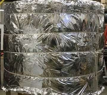
- Insulation blankets
- Vapor barriers and moisture protection
- Thermal protection around penetrations and structural interfaces
Large LNG tank designs can use different insulation arrangements for the bottom, annular space and roof. Project documentation for full-containment tanks describes foam-glass insulation below the inner tank, perlite-filled annular insulation and insulated suspended decks.
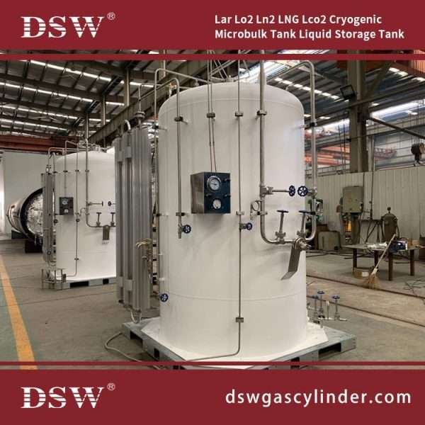
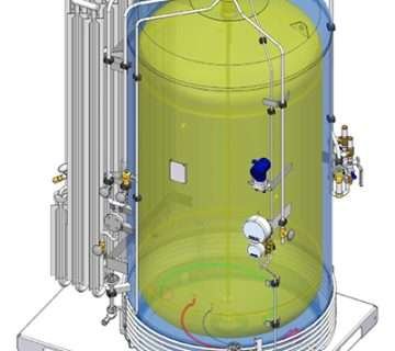
For smaller cryogenic LNG tanks, vacuum insulation may be used. A vacuum-insulated tank generally consists of an inner vessel, outer vessel and evacuated annular space with an engineered insulation system.
However, not all LNG tanks are vacuum insulated. Large terminal tanks generally use different insulation and containment architectures. Vacuum insulation should therefore be considered according to tank scale and application rather than as a universal LNG tank design feature.
Pressure Control and Boil-Off Gas Design
Pressure and BOG management are closely connected and should be engineered as part of the same system.
Even highly insulated LNG tanks receive some heat from the surrounding environment. LNG transfer, flashing, liquid movement and changes in operating conditions can also contribute to vapor generation.
The basic relationship is:
Heat ingress and operating changes → LNG vaporization → BOG generation → pressure control and vapor handling.
Pressure Control
The design must establish normal operating pressure as well as allowable pressure and vacuum conditions.
Pressure may increase because of heat input, LNG filling, flashing and vapor displacement. Conversely, withdrawal or vapor condensation can contribute to reduced pressure.
Pressure and vacuum protection must therefore be integrated into the tank and process design. Applicable pressure-relief and depressuring requirements should be established from the governing standards and project design basis.
BOG Management
Depending on the facility, BOG may be handled through:
- BOG compressors
- Fuel-gas systems
- Recondenser systems
- Vapor-return systems
- Process integration
- Other project-specific recovery systems
Large LNG facilities may use BOG compressors to control vapor generated during storage and LNG transfer operations.
BOG design should consider normal heat leak as well as relevant transient conditions such as filling, unloading, cooldown and changes in operating pressure.
LNG Tank Structural and Foundation Design
The tank structure and foundation must support the combined mechanical and thermal loads produced during filling, storage, withdrawal and other operating conditions.
Structural analysis may consider:
- Hydrostatic LNG load
- Tank self-weight
- Operating and abnormal pressure conditions
- Wind loading
- Seismic loading
- Thermal contraction
- Thermal gradients
- Pipe and nozzle loads
- Settlement
- Other project-specific loads
Foundation Engineering
Foundation design considers soil bearing capacity, settlement, groundwater, seismic conditions and the loads transferred from the tank.
For large LNG tanks, thermal conditions beneath the tank may also need to be controlled. Some designs therefore incorporate foundation heating systems to manage the temperature of the supporting foundation or soil.
Foundation heating is design-dependent and should not be assumed to apply to every LNG tank.
Thermal Contraction and Cooldown
When an LNG tank is cooled from ambient temperature to cryogenic operating conditions, the materials contract. The design must accommodate this movement without creating unacceptable stresses or damaging connections, insulation or piping.
Engineering considerations include:
- Inner-tank contraction
- Movement between structural components
- Pipe and nozzle movement
- Thermal gradients
- Insulation movement
- Cooldown rate
- Thermal stresses
Cooldown and commissioning procedures should be developed specifically for the tank design.
LNG Tank Equipment and Instrumentation
An LNG storage tank is supported by a range of mechanical, process and instrumentation systems.
| System | Typical Function |
|---|---|
| LNG Inlet System | Controls LNG transfer into the tank. |
| LNG Outlet System | Transfers LNG to downstream equipment or process systems. |
| Submerged Pumps | Provide liquid withdrawal where required by the facility. |
| Level Instrumentation | Monitors LNG inventory and supports overfill protection. |
| Pressure Instrumentation | Monitors vapor-space pressure and supports pressure control. |
| Temperature Instrumentation | Monitors LNG and tank temperatures, including cooldown conditions. |
| Relief System | Provides protection against specified pressure and vacuum conditions. |
| Emergency Shutdown | Provides controlled isolation during defined emergency conditions. |
Instrumentation and control systems should be integrated with the overall LNG facility rather than designed independently of the tank process system.
LNG Tank Design Standards and Codes
The applicable LNG tank standards depend on the tank configuration, facility type, location and jurisdiction. There is no single code that automatically applies to every LNG storage tank.
Commonly relevant standards and regulations may include:
| Standard / Regulation | General Relevance |
|---|---|
| API 625 | Tank systems for refrigerated liquefied gas storage. |
| API 620 | Design and construction of large welded low-pressure storage tanks. |
| NFPA 59A | Requirements relevant to LNG facilities in applicable jurisdictions. |
| 49 CFR Part 193 | U.S. federal requirements applicable to certain LNG facilities. |
| ACI 376 | Requirements relevant to concrete structures associated with cryogenic liquid storage. |
API’s standards catalog identifies API 625 as Tank Systems for Refrigerated Liquefied Gas Storage and API 620 as Design and Construction of Large, Welded, Low-Pressure Storage Tanks. The applicable edition should always be verified against the project specification and jurisdiction.
For U.S. LNG projects, API standards may be used together with NFPA requirements and federal regulations such as 49 CFR Part 193.
Important: The standards listed above are examples, not a universal compliance checklist. The final design basis should identify the exact codes, standards, regulations and editions applicable to the project.
LNG Tank Design for Different Applications
| Application | Major Design Considerations |
|---|---|
| Industrial LNG Storage | Capacity, operating pressure, insulation, LNG supply and downstream demand. |
| LNG Fueling Station | Storage capacity, dispensing rate, BOG control and site footprint. |
| Satellite LNG Facility | Transport interface, unloading, storage and downstream vaporization. |
| Peak-Shaving Facility | Long-term storage, rapid withdrawal and BOG management. |
| LNG Terminal | Large capacity, containment, seismic design, BOG systems and loading/unloading integration. |
LNG Tank Design: Engineering Calculations
A detailed LNG tank engineering package may include calculations and analyses for:
- Tank capacity and working volume
- Hydrostatic loading
- Operating and design pressure
- Pressure and vacuum scenarios
- Heat transfer and heat ingress
- BOG generation
- Thermal contraction
- Wind and seismic loading
- Structural stresses
- Foundation loads and settlement
- Pipe and nozzle loads
- Relief-system requirements
- Fatigue or cyclic loading where applicable
The calculation methodology should follow the selected design codes and the project-specific design basis. Generic tank-sizing formulas are not sufficient for final LNG tank engineering.
How to Select an LNG Tank Design
The appropriate LNG tank design should be selected from the complete operating and site requirements rather than storage capacity alone.
Key questions include:
- What LNG capacity is required?
- What are the normal and maximum operating pressures?
- What LNG temperature and composition will be handled?
- What are the filling and withdrawal rates?
- How long will LNG remain in storage?
- What BOG generation and handling requirements apply?
- Is vacuum insulation appropriate for the tank scale and application?
- Which containment configuration is required?
- What soil and foundation conditions exist?
- What seismic and environmental loads apply?
- Which codes and regulations govern the installation?
- What inspection, maintenance and operating requirements must the tank support?
These requirements establish the engineering basis for selecting the tank geometry, containment system, materials, insulation, pressure-control equipment and auxiliary systems.
Cryogenic Tanks FAQs
About LNG Tank Design
LNG tanks require materials that can withstand very low temperatures. Common materials include 9% nickel steel and suitable austenitic stainless steels. Large LNG tanks may also use reinforced or prestressed concrete for the outer containment structure.
Good insulation helps reduce heat entering the tank. This helps limit LNG vaporization, control BOG generation and maintain stable tank pressure. The insulation system must also perform reliably under cryogenic conditions.
BOG means boil-off gas. It is vapor produced when LNG receives heat or when operating conditions cause some liquid to vaporize. LNG tanks therefore need suitable systems to control, recover or safely manage BOG.
No. Many small and medium-sized LNG tanks use vacuum insulation. Large LNG terminal tanks usually use different insulation and containment systems designed for their size and operating conditions.
A full-containment LNG tank has a primary system that holds the LNG and a secondary structure that provides additional containment. The design helps contain both LNG and vapor under specified operating and design conditions.
The applicable standards depend on the project, location and tank design. They may include API 625, API 620, NFPA 59A, ACI 376 and 49 CFR Part 193, along with other national, regional and project-specific requirements.
LNG tanks can place significant loads on their foundations. Cryogenic operation can also create thermal effects. Foundation design therefore considers factors such as soil conditions, settlement, seismic loads, groundwater and the tank’s thermal design.
Related LNG Tank Resources
For a basic explanation of LNG storage technology, see What Is an LNG Storage Tank?
For a comparison of major tank configurations, see Types of LNG Storage Tanks.
For broader information about cryogenic storage equipment, see Cryogenic Tanks Guide.
For transportable cryogenic storage systems, see Cryogenic ISO Tanks.
Conclusion
LNG tank design integrates cryogenic materials, containment, insulation, structural engineering, pressure control, BOG management, foundation design and instrumentation into one engineered system.
The key design relationships are closely connected: material selection determines cryogenic suitability; insulation controls heat ingress; heat ingress contributes to BOG generation; BOG affects pressure management; and tank configuration determines structural and foundation requirements.
A properly engineered LNG storage tank should therefore begin with a clear design basis covering LNG properties, capacity, operating conditions, site characteristics, containment requirements and applicable standards.
Whether the project involves an industrial LNG storage tank, fueling station, satellite LNG facility or large LNG terminal, the final design should be based on project-specific engineering analysis and the current codes and regulations applicable to the installation.


No comment